|
||

|
|
||||||||||||||||||
|
#2362
 10-01-2012
|
||||
|
||||
|
Quote:
But I do believe they are 1/8"
__________________
Kyosho Lazer ZX-RS Kyosho RB5 SP2 WC - Vega Kyosho Mad Force Kruiser VE Kyosho TF6 SP Kyosho Plazma Ra 
|
|
#2363
10-01-2012
|
||||
|
||||
|
This may be more difficult than I expected. It is easy to design the layshaft. But in order to use the hubs or plates on both size of the spur, we might need new hubs, as the current hub on the lazer zx connects directly to the first pulley.
__________________
Kyosho Lazer ZX-RS Kyosho RB5 SP2 WC - Vega Kyosho Mad Force Kruiser VE Kyosho TF6 SP Kyosho Plazma Ra
|
|
#2364
10-01-2012
|
||||
|
||||
|
Quote:
__________________
www.kamtec.co.uk www.fibre-lyte.co.uk answer-rc.com/uk/en/ Answer UK team driver Designer of the Lazer ZX/ZXR carbon fibre tub chassis Designer of the Lazer ZXRS
|
|
#2365
10-01-2012
|
||||
|
||||
|
Quote:
__________________
www.kamtec.co.uk www.fibre-lyte.co.uk answer-rc.com/uk/en/ Answer UK team driver Designer of the Lazer ZX/ZXR carbon fibre tub chassis Designer of the Lazer ZXRS
|
|
#2366
10-01-2012
|
||||
|
||||
|
Quote:
__________________
www.kamtec.co.uk www.fibre-lyte.co.uk answer-rc.com/uk/en/ Answer UK team driver Designer of the Lazer ZX/ZXR carbon fibre tub chassis Designer of the Lazer ZXRS
|
|
#2367
10-01-2012
|
||||
|
||||
|
Ive got to thank rondoola for his help in saving the day for me and has a couple of Tough racing belts that he can get to me before friday so now I can race my ZXR on Sunday.
 Next phase is the rear gearbox design to tension the rear belt so we can stop this happening. Then when done all that is needed is developing the layshaft and slipper system which sounds a big job but in reality is most probably very easy. 
__________________
www.kamtec.co.uk www.fibre-lyte.co.uk answer-rc.com/uk/en/ Answer UK team driver Designer of the Lazer ZX/ZXR carbon fibre tub chassis Designer of the Lazer ZXRS
|
|
#2368
10-01-2012
|
|||
|
|||
|
i just opened up my front diff and measured the ball size, its exactly 3mm. I also need help regarding kyosho ball diffs. i heard in 1992 kyosho upgraded their ball diff design using seperate diff rings that can be flipped, but still using the same diff outdrives. in order to use these new diff rings, a special spacer was needed to hold the rings. anyone know the part number of these spacers and the rings? Are the rings WBD-4? In the ZX-r Manual, if i am not mistaken, the spacers are marked 59. What is the part number for me to get these spacers? Please do correct me if i am wrong. Lastly look at my Optima MId ball diff pictured here, this is the old diff rings right ?
Also i got a suggestion regarding the Lazer shaft with longer spring. After you make the shaft longer with the spring sticking out, how are you going to cover the nut and the longer shaft? I solved this problem with my B4 optima mid slipper, by reaming a hole on the center of my gear cover, then using a chinese medicine bottle, used a hot knife to split it to the length i want, then insert it into the gear cover, placed some silicon to seal it, then superglued it. The result is a B4 type gear cover, with a tight fitting cap that can be removed to adjust the slipper tension, very useful at the track !
|
|
#2369
10-01-2012
|
||||
|
||||
|
Quote:
Maybe I am working off of a Lazer ZX. But if you look at the following pictures:   Circled in red is the plate that I am concern about. On the Lazer, the part that is circled in red have a particilar spline that attaches to the pulley that I have yet to find out what is it. On the B4, we are missing the spline. Currently, the only easy way is to increase the diameter of the thrust plate on the Lazer to the same size as the B4 (which I have said in a few earlier post) and glue the thrust plates to the hub. It is possible to create a plate like the B4 and have the connecting part to the pulley, but it would cost an arm and a leg. If for some reason, we are thinking about using the locking mechanism from the B4 plate to turn the layshaft, then there will be no need for the one-way bearings in the original Lazer hubs. All of the things I am talking about is about the Lazer ZX only, I am not sure the difference about the other Lazers. Please correct me if I am wrong, I am still kinda confused. =)
__________________
Kyosho Lazer ZX-RS Kyosho RB5 SP2 WC - Vega Kyosho Mad Force Kruiser VE Kyosho TF6 SP Kyosho Plazma Ra
|
|
#2370
10-01-2012
|
||||
|
||||
|
Quote:
yeah its possible to get those but they come in an set with new outdrives also wbd-4 are the diff washers.
|
|
#2371
10-01-2012
|
||||
|
||||
|
Quote:
Maybe just cut of the innerplate and make the outer part of the shaft B4/rb5 look alike ... On the hypercluth they have just macined it down so the slipper new slipper plate fits. mvh isobarik
|
|
#2372
10-01-2012
|
||||
|
||||
|
Can anyone answer me why we need oneway bearings inside the hubs?
Isn't it the same as locking the pulleys to the layshaft?
__________________
Kyosho Lazer ZX-RS Kyosho RB5 SP2 WC - Vega Kyosho Mad Force Kruiser VE Kyosho TF6 SP Kyosho Plazma Ra
|
|
#2373
10-01-2012
|
||||
|
||||
|
__________________
Kyosho Lazer ZX-RS Kyosho RB5 SP2 WC - Vega Kyosho Mad Force Kruiser VE Kyosho TF6 SP Kyosho Plazma Ra
|
|
#2374
10-01-2012
|
||||
|
||||
|
Quote:
__________________
www.kamtec.co.uk www.fibre-lyte.co.uk answer-rc.com/uk/en/ Answer UK team driver Designer of the Lazer ZX/ZXR carbon fibre tub chassis Designer of the Lazer ZXRS
|
|
#2375
10-01-2012
|
||||
|
||||
|
Quote:
__________________
www.kamtec.co.uk www.fibre-lyte.co.uk answer-rc.com/uk/en/ Answer UK team driver Designer of the Lazer ZX/ZXR carbon fibre tub chassis Designer of the Lazer ZXRS
|
|
#2376
10-01-2012
|
||||
|
||||
|
Quote:
I am working off of a Original Lazer ZX hubs. I didn't know that the MKII hubs have 2 parts. Is there a part number for it so that I can do some reseach on it? which manual is it on? Is this the one you are talking about? 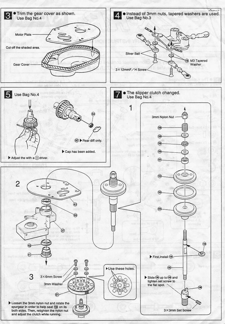
__________________
Kyosho Lazer ZX-RS Kyosho RB5 SP2 WC - Vega Kyosho Mad Force Kruiser VE Kyosho TF6 SP Kyosho Plazma Ra
|
|
#2378
11-01-2012
|
||||
|
||||
|
Quote:
WBD-2 Is a ball set, WBD-3 is the diff casing and WBD-4 are the 2 pressure plates.
__________________
Trader Feedback ==> http://www.oople.com/forums/showthread.php?t=154468 1/10 Kyosho Lazer ZX 1/10 Kyosho Optima Mid Custom
|
|
#2379
11-01-2012
|
||||
|
||||
|
Quote:
__________________
www.kamtec.co.uk www.fibre-lyte.co.uk answer-rc.com/uk/en/ Answer UK team driver Designer of the Lazer ZX/ZXR carbon fibre tub chassis Designer of the Lazer ZXRS
|
|
#2380
11-01-2012
|
|||
|
|||
|
If a day I will be able to build my dream slipper I will start using a 3M 14 teeth HDT pulley bar in order to get rid of both LA11 and the front one way.
Then I will cut the bar at the desired lenght and machine both ends in order to fit the two large bearings. I will drill a hole in the middle in order to fix the pulley section to the axle with a grub screw. Obviously the axle that will go inside the pulley section has a end section to fit the B4 slipper  . .Can you figure out the whole assembly without a cad drawing ? Here's the link of the pullay bar http://shop.polybelt.com/3M-14-Pulle...3M-14-100A.htm Bye Ema P.S. In my dreams the pulley will also be hard anodyzed  . .
|
 |
| Thread Tools | |
| Display Modes | |
|
|


 Linear Mode

