|
||

|
|
||||||||||||||||||
|
#1
 20-05-2009
|
|||
|
|||
|
Just finished building my B44 - then spent huors trying to fit the ESC, receiver, motor along with all the cables.
What felt like a tight squeeze on some of them, and im not 100% happy with the cable's etc. Just wondering if anyone has any photo's of their B44's with the body shell off? thanks. 
|
|
#2
20-05-2009
|
||||
|
||||
|
Hope this helps you - this was prior to Lipo batts of course but apart from that all the same
Regards Tony Evdoka
__________________
|
|
#4
04-11-2009
|
||||
|
||||
|
This is how I do mine, I think it's a pretty common way of doing it.
Note that you can use the stock aerial mount in the corner - the plastic is soft enough that threading in the 4-40 screw is no prob. Also, make sure that you can still see the programming lights on your esc if poss. I like to put the switch under the "cheeks" of the body, since you can reach in and switch the car on or off easily w/o removing the body.  Cheers, Ty 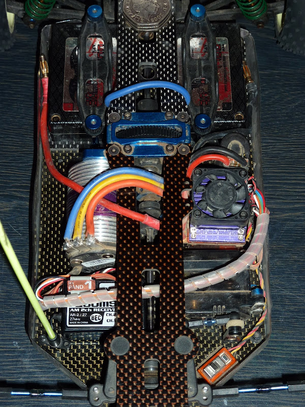
|
|
#5
04-11-2009
|
||||
|
||||
|
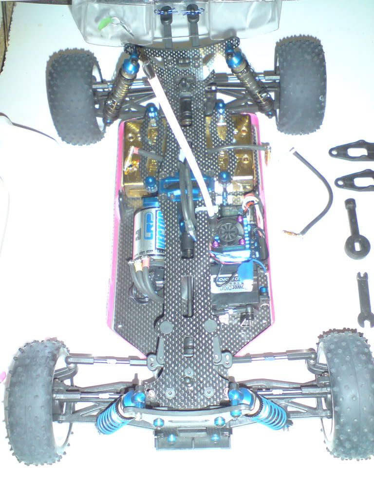
I made my wiring a mission when I installed the speed passion brushless gear. I'd run my dad's GTB for a bit so got an idea of where I wanted to route things and what problems I hit with positions, etc.
I wanted the wiring to be perfect and make everything else easy to work on. Also keep the motor wires short to reduce any power loss. The sensor wire is a little annoying since the 90mm supplied wire is a touch too short and the 180mm one is a bit too long. if only they made a 120mm sensor wire... The beauty of solder posts if you can solder the motor wires on upside down if you want. I did this purely to get the motor wires as low as possible and therefore they would travel under the centre shaft. You could do with with the speed rotated if you wanted, but they would be longer if facing the rear and up against the servo if facing the front. I tied up the excess servo/PT wire with the speedo-reciever wire and routed it tidy under the shaft. the biggest niggle I had when I ran my wires either over the top of the top deck or between the shaft and deck was it was a pain in the ass to remove the slipper/spur assembly. Running the wires tidily under it solves this. The V3 motors genius plugs make it easy to get them running where you want them to go. Wire the speedo mounted like I have it also gives easy access to pop out the receiver wire and plug in the spare when connecting the programmer unit. The battery wires are kept out of the way and secure so they don't rub on the spur. Since you can't see it in the pictures the power cap (or K.E.R.S as my dad calls it...) is mounted under the slipper on the chassis. I hated the GTB cap since it's so big. the GT2.0's being 2 smaller ones makes it easy to hide it away. anyway here are some pics.   
__________________
 CML Distribution - Distributors of Quality Radio Control Models & RC Hobby Products
|
|
#6
05-11-2009
|
||||
|
||||
|
Quote:
|
|
#7
05-11-2009
|
||||
|
||||
|
soldered them on upside down. I'll remove the top deck so you can see easier when I get home.
When I ran the GTB I had the motor wires between the speedo and the servo. the case of the servo held the wires in place so they came out and did 180 degrees then got held between the 2 and then ran under the shaft. that was with the SP v3.0 motor so I had the plugs to help with that. I wouldn't have thought coming up and being soldered on from below would be too hard though. The GTB has solder tabs so if you fancied it you could swap them onto the otherside. Since the one I had was my dad's I didn't change them.
__________________
CML Distribution - Distributors of Quality Radio Control Models & RC Hobby Products
|
|
#8
05-11-2009
|
|||
|
|||
__________________
Stewart Baldridge -------------------- Nemo Racing Yokomo Yz-2. Yokomo Yx-4sf Sanwa http://www.oople.com/forums/showthread.php?t=158845
|
|
#9
06-11-2009
|
||||
|
||||
|
Quote:
 
__________________
CML Distribution - Distributors of Quality Radio Control Models & RC Hobby Products
|
|
#11
12-11-2009
|
||||
|
||||
|
shame my speedo gave up right after I took the pics. it's winging it's way back to Schumacher under warranty.

__________________
CML Distribution - Distributors of Quality Radio Control Models & RC Hobby Products
|
|
#12
12-11-2009
|
||||
|
||||
|
Quote:
Yeah, you should be fine - cool layout nonetheless. Must be tons of wires jammed under there though - sensor x6, speedo control x3, servo x3, pt x2, fan x2, switch x3, cap leads x2, drive wires x3! Cheers, Ty
|
|
#13
13-11-2009
|
||||
|
||||
|
the tabs were never resoldered. I just soldered the wires on pointing down rather than the usual up. Once the wires were removed it looks the same as any other.
__________________
CML Distribution - Distributors of Quality Radio Control Models & RC Hobby Products
|
|
#14
07-12-2009
|
||||
|
||||
|
Quote:

|
|
#15
07-12-2009
|
||||
|
||||
|
mine now lives next to the spur behind one of the body posts away from any impact turning it off.
__________________
CML Distribution - Distributors of Quality Radio Control Models & RC Hobby Products
|
|
#16
31-07-2010
|
||||
|
||||
|
thought i would ressureect an old thread seeing as i took some pics today
 
|
|
#17
31-07-2010
|
||||
|
||||
|
The only trouble I found was having your motor wires there made removing the spur a pain in the arse
__________________
CML Distribution - Distributors of Quality Radio Control Models & RC Hobby Products
|
|
#19
08-09-2010
|
|||
|
|||
|
Quote:
Couple of questions: For the battery and motor wires are you just using gravity to stop them from hitting the shafts or have you secured them some other way ? What brand of body and wing is that ? What sort of bullet connectors do you use to get such a neat low-profile setup ?
|
 |
| Thread Tools | |
| Display Modes | |
|
|


 Team Associated


 Linear Mode

